The yellow was read on the delivery table
The pale yellow field was not a reason to move the keys. On the white backing, zone 3 was 1.83 ΔE*ab from the CD1 yellow aim and zone 4 was 0.99, both inside the deviation of 5 in ISO 12647-2:2013 Table 7.
The buyer tapped the pale yellow field with a finger and said it looked dirty. The sheet he tapped was still on the steel of the delivery. That is the wrong surface for the number he wanted, and I did not write down whatever the instrument would have said there.
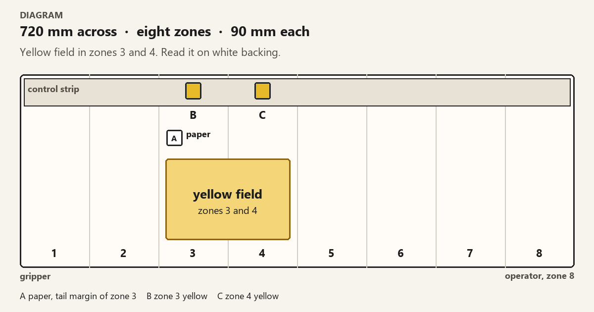
The job was a magazine cover, sheet-fed offset, wood-free coated gloss, 130 g/m². Four process colours, printing condition PC1. In ISO 12647-2:2013, Table 1 pairs PC1 with print substrate PS1 and colorant description CD1. Table 2 puts premium coated stock from 80 to 250 g/m² in PS1, and 130 sits in that range, so the paper aim I used is the white-backing row: L* 95, a* 1, b* -4, tolerances ±3, ±2, and ±4. The yellow he was pointing at lives in zones 3 and 4, a flat field, not a picture that hides in one corner. Eight keys across a 720 mm sheet, 90 mm each. The field starts about 180 mm in from the gear side and runs two zones. His complaint was the field. The reading had to be the field.
The delivery table is not a backing
Clause 4.3.2.3 says the process-colour solids shall agree with the white-backing aims in Table 5, within the deviation tolerance in Table 7. The same clause says they should agree with the black-backing aims. "Shall" is the white-backing column. "Should" is the black one. Clause 4.3.6 note 4 allows a conformance reading on either backing. It does not allow a white-backing aim under a reading taken over dark steel. The delivery table behaves like a dark backing. I picked the sheet up and put it on the white backing board we use for the WB columns, and I set the instrument before I believed it.
The instrument is 0:45. ISO 12647-2:2013, in the note under Table 5, asks for ISO 13655, D50, 2° observer, geometry 0:45 or 45:0, and says measurements should be made using M1. Ours was already on M1, D50, 2°. PS1 is listed in Table 2 as moderate fluorescence, so M0 left over from another stock would not be the same reading. I looked. It said M1. One instrument for the paper and both yellow solids.
Clause 4.3.1 requires the ink set to be to ISO 2846-1 and the printing sequence to be black, then cyan, then magenta, then yellow. The units were in that order. I checked because a yellow printed under the wrong unit will still give you a yellow square in the strip, and the CD1 yellow numbers will not describe it. The cans matched the ticket. That did not finish the argument. An ISO 2846-1 yellow is not yet a CD1 solid on this sheet.
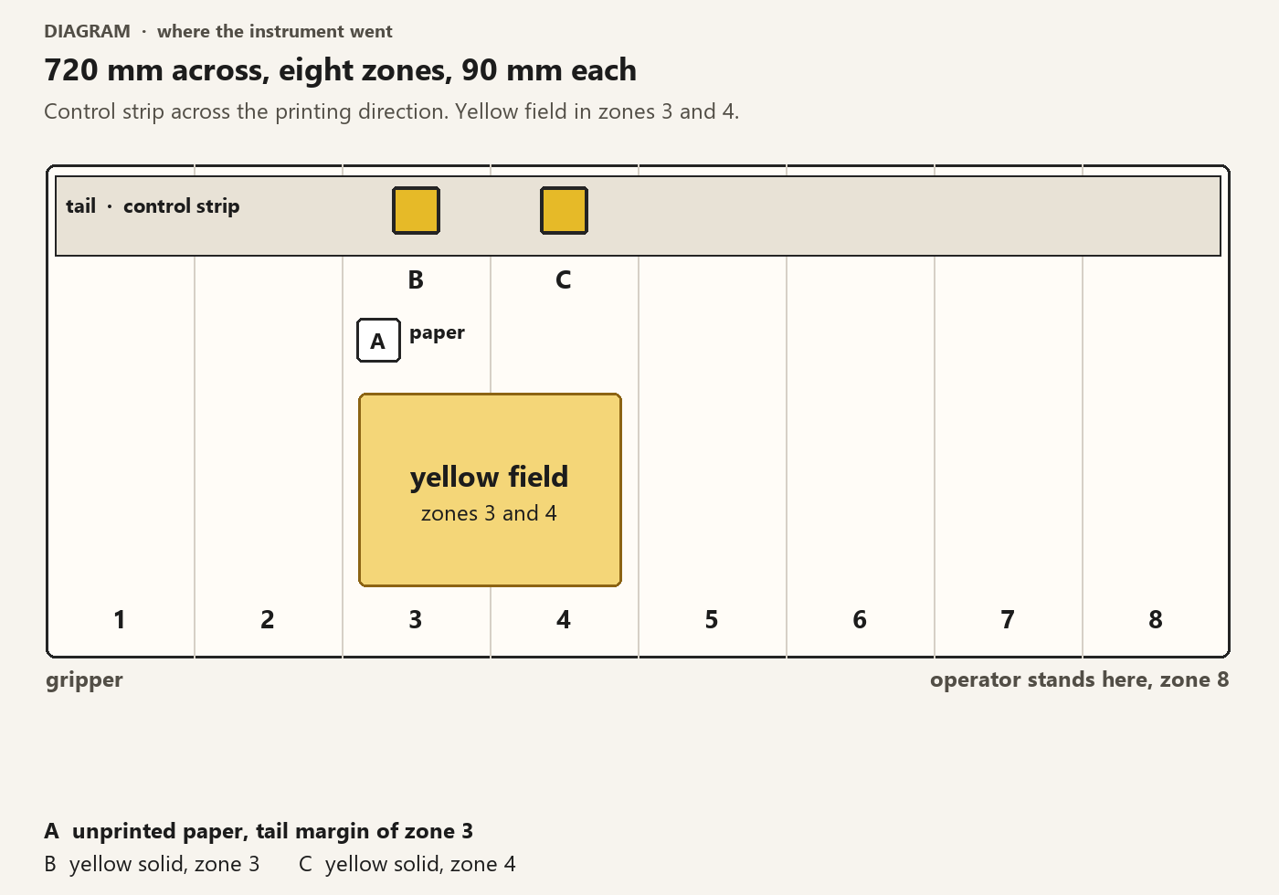
On that drawing the field is zones 3 and 4. A is unprinted paper in the tail margin of zone 3. B is the yellow solid in the strip in zone 3. C is the yellow solid in zone 4, because the field crosses the key boundary. The strip runs the tail, across the printing direction, zone 1 through zone 8. Clause 4.3.6 requires that strip, covering the ink zones the image uses. A strip down the side of zone 1 would have been the extra strip in note 6, not the one this field is judged on. The operator stands at zone 8. The field is not at his elbow. He had walked over, which is why the sheet ended up on the steel in the first place. He set it down to point. I picked it up to measure.
Paper, then the yellow, on the white board
Table 2, PS1, white backing: L* 95, a* 1, b* -4. Tolerances ±3 on L*, ±2 on a*, ±4 on b*. The b* window is wider than the ±2 printed for the other coated rows in that table. I used ±4 because that is the PS1 cell, not because I wanted room.
Unprinted paper in the tail margin of zone 3, M1, D50, 2°, 0:45, white backing: L* 94.6, a* 1.2, b* -3.2.
Against 95, 1, -4 that is 0.4 low on L*, 0.2 high on a*, and 0.8 short of the blue aim on b*. All three sit inside ±3, ±2, ±4. The stock is not the dirt he saw. I said so, because a yellow complaint on a sheet that is already a bit warm in b* is how a paper problem gets blamed on the ink. This paper is inside. The ink gets its own reading.
CD1 yellow, white backing, dry sheet, from Table 5: L* 89, a* -4, b* 93. Black backing for the same colorant: L* 87, a* -4, b* 91. Two L* and two b* between the columns, and a* does not move. That gap is why this complaint, of all the colours, is the one a dark table can fake. CD1 cyan moves less: white backing 56, -36, -51, black backing 55, -35, -51. One L* and one a*. CD1 black is 16, 0, 0 on both backings. Black will not tell you that the sheet was on the steel. Yellow will.
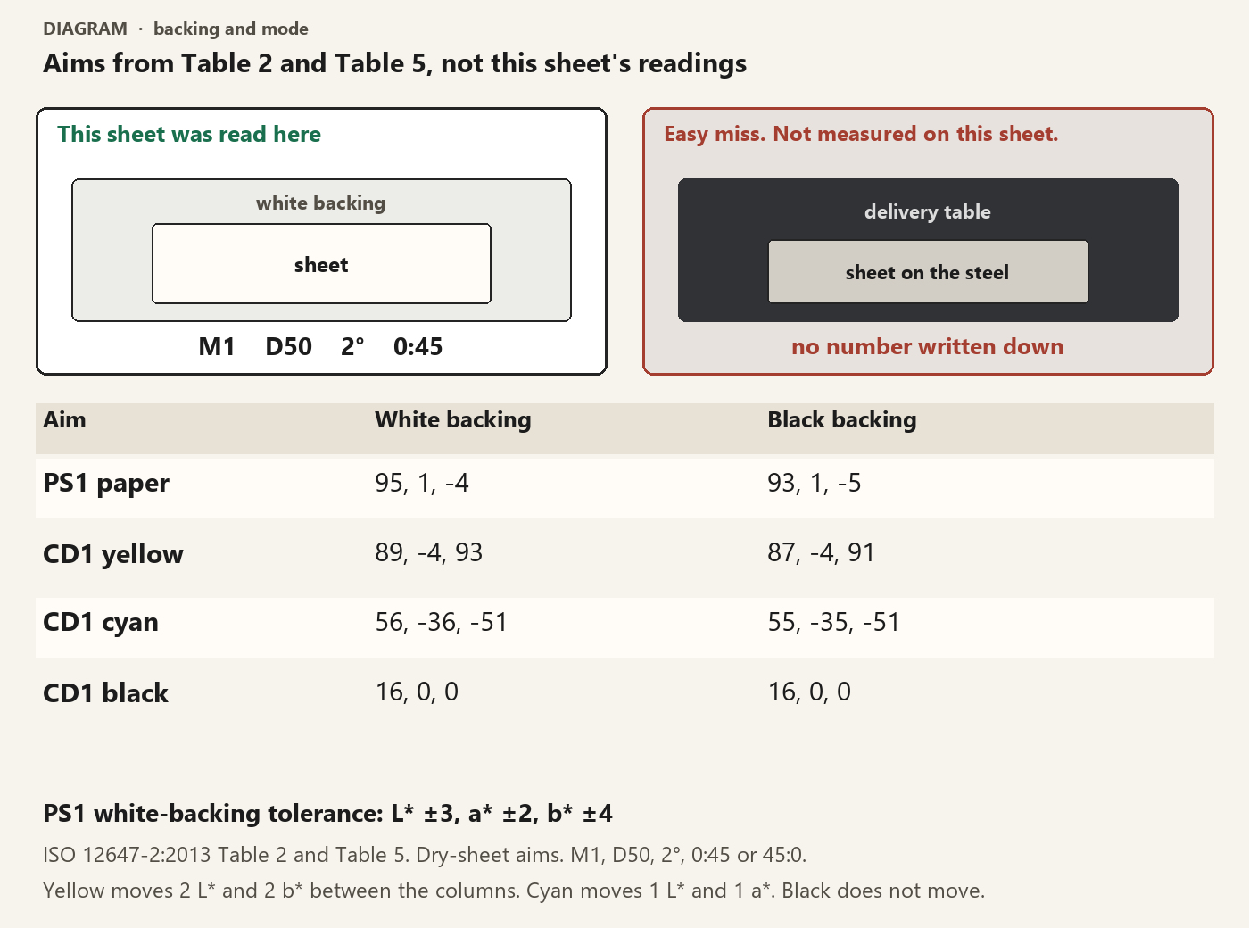
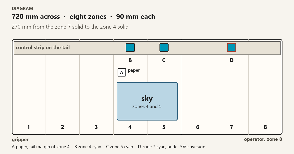
The left side of that drawing is how this sheet was read. The right side is the miss, and I did not record a number from it. Under the drawing the aims are the standard's two columns. PS1 paper, white backing 95, 1, -4, black backing 93, 1, -5. CD1 yellow, 89, -4, 93 and 87, -4, 91. CD1 cyan, 56, -36, -51 and 55, -35, -51. CD1 black, 16, 0, 0 and 16, 0, 0. The tolerance I used on the paper is the PS1 white-backing row, L* ±3, a* ±2, b* ±4.
Zone 3 yellow solid, same instrument, same board, same M1: L* 88.2, a* -3.6, b* 91.4.
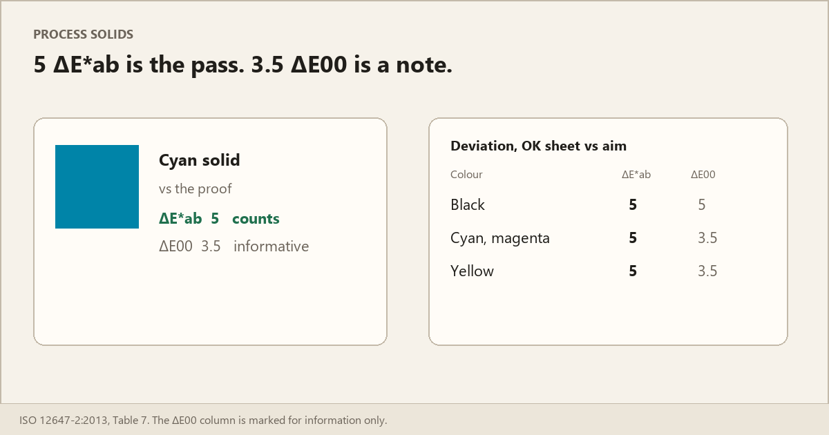
Against 89, -4, 93 the differences are ΔL* -0.8, Δa* 0.4, Δb* -1.6. Squares 0.64, 0.16, 2.56. Sum 3.36. Square root 1.83. That is ΔEab, the ΔEab column of Table 7. The deviation tolerance for yellow on the OK print is 5 ΔEab. Beside it the table prints 3.5 ΔE00, and the footnote says the ΔE00 values are information only. 1.83 is inside 5. I did not convert 1.83 into a CIEDE2000 figure at the bench and then hold it against 3.5. There was no need to swap columns. The solid was already inside the normative deviation by a wide margin.
Zone 4, the other half of the field: L* 88.6, a* -3.9, b* 92.1.
Differences from the same aim: ΔL* -0.4, Δa* 0.1, Δb* -0.9. Squares 0.16, 0.01, 0.81. Sum 0.98. Square root 0.99. Also inside 5. The two zones are the same yellow seen from adjacent keys, not a second fault. If I had pulled zone 3 and left zone 4, the field would have grown a stripe on the boundary. I did not pull either. They both sit with the aim.
In words, zone 3 is 0.8 L* darker than 89, 0.4 less green than -4, and 1.6 short of b* 93. That is a small, slightly duller yellow, not a dirty one in the sense that would push a key. Zone 4 is even closer. The dirt he thought he saw was the sheet on the steel, with the delivery lamps on it, and a finger in the way.
He had not tapped the solid. He had tapped the field, and the field in the file is not a 100% yellow. It is a tint. A tint on coated paper shows the sheet through the screen, and a tint lying on dark steel shows the steel as well. Table 5 is the solid. The solid is the patch in the strip, B and C, not the middle of the picture. Cleaning a tint by adding solid ink is how a passing yellow becomes a heavy one. The paper under that tint is already inside ±3, ±2, ±4. I was not going to feed zone 3 to hide a backing.
The red overprint patch was sitting in the same strip, and someone was going to drag it into the argument because the field has a warm edge where a little magenta kisses the yellow. Table 5 does print a red for CD1 on white backing, L* 48, a* 68, b* 47, and the clause says the two-colour overprints should agree with that table. Should. Note 4 under those colour clauses says it is not possible to state tolerance windows for both the solids and the overprints. Table 7 has no red row. I did not fail the sheet on the red patch, and I did not invent a ΔE*ab limit for it. The yellow solids were the complaint, and they were inside 5.
Table 7 also lists a variation tolerance for yellow of 5 ΔE*ab, and 3.5 ΔE00 again only as information, and a ΔH of 3. The variation column is for production copies against an OK sheet, for at least 68% of them. We do not have a signed OK sheet. I did not use that column, and I did not calculate ΔH on a solid that was already at 1.83. Black's ΔH cell is a dash. Yellow's is 3. It did not decide this sheet.
| Place on this sheet | L* | a* | b* | Aim, white backing | Result |
|---|---|---|---|---|---|
| Paper, tail margin of zone 3 | 94.6 | 1.2 | -3.2 | PS1 95, 1, -4 | inside ±3, ±2, ±4 |
| Yellow solid, zone 3 | 88.2 | -3.6 | 91.4 | CD1 89, -4, 93 | 1.83 ΔE*ab, inside 5 |
| Yellow solid, zone 4 | 88.6 | -3.9 | 92.1 | CD1 89, -4, 93 | 0.99 ΔE*ab, inside 5 |
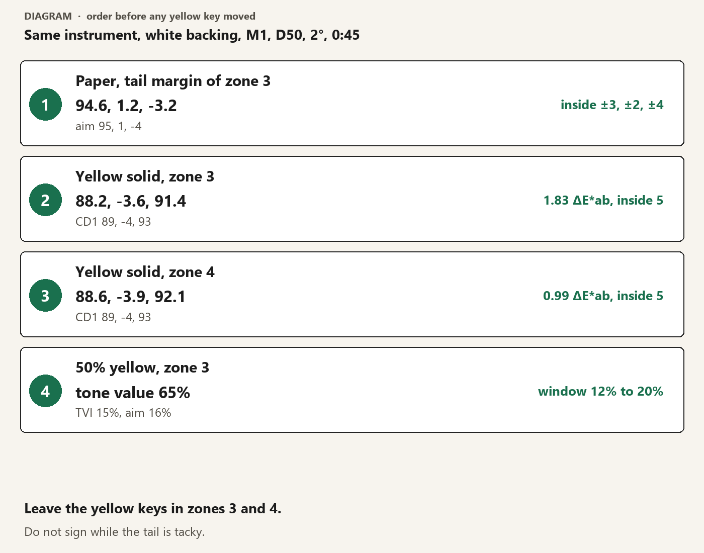
That is the order. Paper, the field, the other half of the field. The 50% patch is last.
The mid-tone did not get a vote over a solid that was already inside
Table 8, PC1, periodic screens, 50% patch: tone value increase 16%. The plates on this job are periodic, round dot, 70 cm-1, inside the 60 cm-1 to 80 cm-1 in clause 4.3.3 for coated work. The non-periodic half of the same PC1 row, at 50%, is 28%. I was not going to call a periodic patch against 28. The 40% aim on the periodic row is 15, the 75% aim is 13, the 80% aim is 11. I only needed the 50% patch, and I needed the periodic number.
Table 11, for a control patch from 30% to 60%, deviation tolerance 4 percentage points. The window around 16 is 12% to 20%. The 50% yellow patch in zone 3 read a tone value of 65%. The file value is 50%. TVI is 15%. Fifteen sits inside 12 to 20. Table 8 note 1 says those aims are densitometry to ISO 5-3, Status E, no polarisation. The polariser was out. Status T, note 2 says, comes out close on standard inks. I did not use "close". The instrument was on Status E.
Fifteen inside the window means I do not open a plate curve because a buyer called the field dirty. The solid is inside 5 ΔE*ab of CD1 on the backing the table actually requires. The mid-tone is behaving. Clause 4.3.2.3, in the note on density, says density is for holding a run after the solids are right, read off the OK sheet with the same instrument, the same ink and the same paper. Yesterday's density was still sitting in the console from the previous form. I did not bring it into this argument. There is no yellow density aim in ISO 12647-2:2013 for me to have used anyway.
Table 5 values are for dry sheets. The tail on this pull was still a little tacky at the corners. Note 5 of clause 4.3.6 says conformance readings can be made on dry sheets, after a time that depends on the process and the materials. The standard does not give me a dryback number to add to 1.83 or subtract from it. A tacky sheet can move. This one was not outside the deviation, so I was not looking at a miss that had to be chased before it dried. I also was not going to sign the OK line across a tacky tail. I pencilled the white-backing numbers in the margin — paper 94.6, 1.2, -3.2; zone 3 yellow 88.2, -3.6, 91.4, 1.83; zone 4 yellow 88.6, -3.9, 92.1, 0.99; 50% yellow TVI 15% — and I left the signature empty.
The keys did not move. Zone 3 and zone 4 stay where they are. When a dry sheet is read, it is read on the same white board, M1, D50, 2°, 0:45, against 89, -4, 93, deviation 5 ΔE*ab. Not against the steel. Not against the black-backing column 87, -4, 91. Not against the informative 3.5 ΔE00. The 50% patch, if anyone reopens it, is still the periodic aim of 16%, window 12% to 20%, Status E, polariser out.
He could still dislike the field under the delivery lamps. That is a viewing argument, and it is not the solid. The solid, on the backing Table 5 was built on, is inside the deviation. I am not going to dirty a passing yellow to satisfy a sheet that was lying on the steel.