The light cyan was in zone 7. The sky is in zone 4.
On this coated cover the light cyan was zone 7, 4.17 ΔE*ab from the CD1 aim and inside the deviation of 5 in ISO 12647-2:2013 Table 7. The sky sits in zone 4 and zone 5, at 7.76 and 7.19, so those two keys came down and the zone 7 key stayed where it was.
He had the cyan key for zone 7 between his fingers before the instrument was out of the case. The solid at his end of the sheet looked thin. He was right about that patch. The sky he was trying to feed does not sit in zone 7.
The job was a catalogue cover, sheet-fed offset, wood-free coated gloss, 150 g/m². Four process colours. The sheet was 720 mm across the ink keys, eight keys, 90 mm each. The sky is a flat cyan field that starts in zone 4 and runs through zone 5. From the middle of the zone 7 solid to the middle of the zone 4 solid is 270 mm. That is the whole argument. The ink he was about to add sits 270 mm from the zone 4 solid, in a zone the picture does not use.
I told him to leave the key where it was until I had read three places: the unprinted paper in the tail margin of zone 4, the cyan solid in zone 4, and the cyan solid in zone 5. Zone 7 could wait. It did not get to vote on the sky.
The ticket was PC1, which is a short list of aims
The ticket said PC1. In ISO 12647-2:2013 that is not a mood and it is not a density. Table 1 pairs printing condition PC1 with print substrate PS1 and colorant description CD1. PS1, in Table 2, is premium coated: mass-per-area 80 to 250 g/m², the colour coordinates in that table given against the 115 g/m² in brackets. Our 150 g/m² sits inside 80 to 250, so I used the PS1 white-backing paper aim, L* 95, a* 1, b* -4. I did not go hunting for a different paper type because the sheet was heavier than 115. Heavier than the bracket and still inside the range is still PS1.
Table 2 calls the fluorescence of PS1 moderate. That one word is why the instrument mode had to be looked at before the first reading. A moderate optical brightener will not read the same under two UV settings. The table says the colour measurement is in accordance with ISO 13655, D50, 2° observer, geometry 0:45 or 45:0, and that measurements should be made using M1. Ours is a 0:45 instrument. I set M1, D50, 2°. It was already there. If it had still said M0 from the uncoated job the day before, I would have stopped and changed it before I believed a single patch. I am not going to invent a colour difference for that mistake. I only know the two modes are not the same reading on this stock, and PS1 is the stock Table 2 marks as moderate.
Clause 4.3.1 says the ink set for these printing conditions shall be to ISO 2846-1, and the printing sequence shall be black, then cyan, then magenta, then yellow. I looked at the units. They were in that order. The cans on the shelf were the ISO 2846-1 set named on the ticket. That check took a minute, and it saved me from a longer argument later. An ink that was sold against ISO 2846-1 is not a finished solid on this sheet. The solid still has to land on CD1. People hear "the ink is ISO" and stop measuring. The ink standard gets the colourant into the ballpark. Clause 4.3.2.3 is the clause that tells you where the solid has to be once it is on the paper.
The plates were periodic, round dot, 70 cm-1. Clause 4.3.3 puts coated work at a screen ruling of 60 cm-1 to 80 cm-1, with a 20 µm spot, and asks the half-tone to carry from 2% to 98% in a consistent way. We were inside the ruling. I was not on this sheet to argue about a 1% dot in a shadow. The complaint was a solid, in a sky, in two ink zones.
The strip is across the tail, and the sky is not at his elbow
The control strip sits on the tail and runs from zone 1 to zone 8, across the printing direction. Clause 4.3.6 requires a control strip in conformance with ISO 12647-1, positioned that way, covering every ink zone the printed image uses. A strip down the side of the sheet, in the printing direction, is something else. Note 6 of that clause allows an extra strip in the printing direction only as additional evaluation, and only where that zone has enough ink to make the reading mean something. If I had judged this cover from a side strip in zone 1, I would have been reading a margin the sky never enters.
He was standing at the zone 8 end, which is where the delivery lets you stand without walking around the pile. The nearest cyan solid in the strip is zone 7. It is a clean square of ink. It looks like the patch you are supposed to read, because it is the patch you can reach. On this form zone 7 carries a trim mark and nothing else. Coverage of every colour in that zone is under 5%. Note 2 of clause 4.3.6 says an ink zone with area coverage less than 5% for each colour can be left out of the conformance evaluation. The solid in the strip is still printed. The press still has a key for it. The patch will still give you a number. The number is not the sky.
The sky occupies zone 4 and zone 5, full enough that neither zone is anywhere near that 5% exclusion. Those two solids are the solids I have to read. Zone 6 on this form is blank margin. It does not get averaged into the sky.
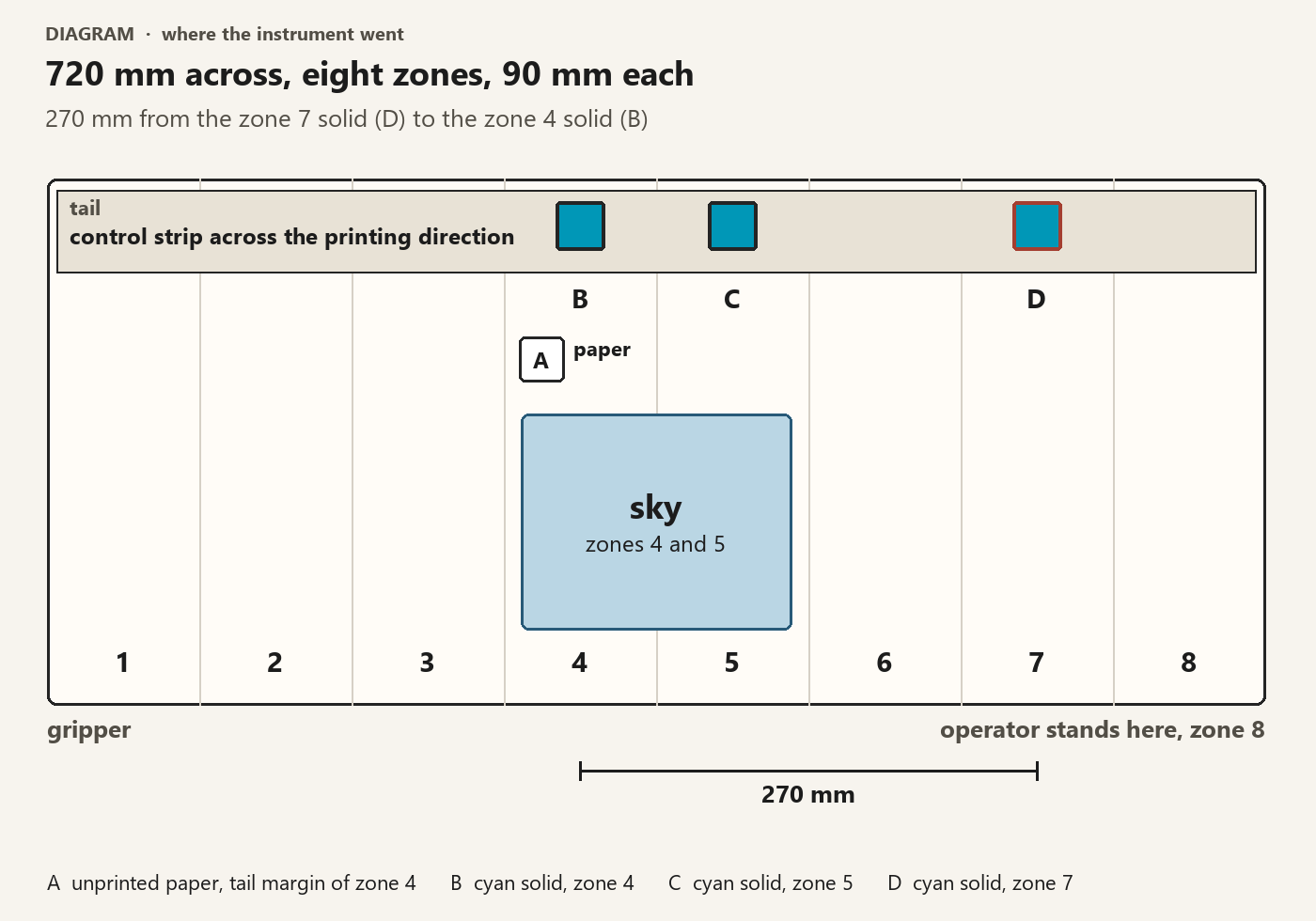
The places on that drawing are the places I actually put the instrument. A is unprinted paper in the tail margin of zone 4, on the sheet, off the picture. B is the cyan solid in the strip in zone 4. C is the cyan solid in zone 5, because the sky crosses the boundary and one key will paint a stripe if the other key stays put. D is the cyan solid in zone 7, the one under his hand. Gripper at the bottom, tail at the top, strip on the tail. The operator's side is zone 8.
I read them in that order. Paper, then the sky, then the patch that had tempted him. Not the other way round. If you start at D, D will talk you into a key move before you have seen B.
Paper first, because a bad white makes a liar of the cyan
Clause 4.3.2.1 and Table 2 are the paper. For PS1 on white backing the aim is L* 95, a* 1, b* -4, with tolerances ±3 on L*, ±2 on a*, and ±4 on b*. The b* tolerance is wider than the ±2 on the other coated rows in that table. I used ±4 because that is what Table 2 prints for PS1, not because a looser number is more comfortable.
The sheet went onto a white backing before any of this. One sheet on the dark delivery table is not that backing. Clause 4.3.6 note 4 allows conformance readings on white backing or on black backing. It does not allow a white-backing aim under a black-backing reading. Table 5 prints both columns for a reason.
I put a white backing board under the sheet, the same board we use when we measure against the WB columns, and I read A.
Unprinted paper in the tail margin of zone 4, M1, D50, 2°, 0:45, white backing: L* 94.2, a* 0.8, b* -3.4.
Against 95, 1, -4 that is 0.8 low on L*, 0.2 low on a*, and 0.6 short of the blue aim on b*. All three sit inside ±3, ±2, ±4. The paper is not the reason the sky looks wrong. I said so out loud, because otherwise the next bad solid becomes "the stock is off" and we start a paper argument we do not have.
The paper check is also where a backing mistake shows up while the cyan still looks harmless. Table 2's own two columns for PS1 are white backing 95, 1, -4 and black backing 93, 1, -5. Two L* and one b* just from the backing the table was measured on. Table 5's CD1 cyan moves less: white backing 56, -36, -51, black backing 55, -35, -51. One L* and one a*. CD1 yellow moves like the paper, not like the cyan: white backing 89, -4, 93, black backing 87, -4, 91. Two L* and two b*. CD1 black is 16, 0, 0 on both backings. Black will not warn you. Yellow will. Cyan, on this colorant, almost will not.
So if I had been careless with the backing on this particular complaint, the cyan number would have shifted by about the gap between those two columns, which is small beside the miss I found in zone 4. I still refused to read on the console. The paper check was the first reading, the paper tolerances are tight enough that two L* matters, and the next job on this press may be a yellow complaint. The habit is the backing, every time, before the argument about which colour is guilty.
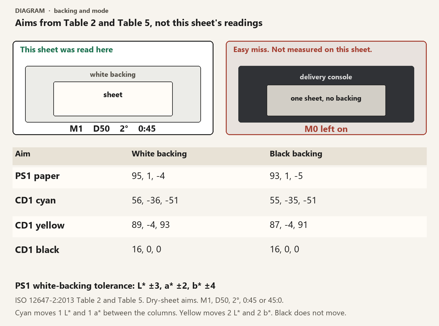
The drawing is the two setups, and under them the aims from Table 2 and Table 5, not the readings off this sheet. Left side is how this sheet was read. Right side is the miss: one sheet on the delivery, mode still on M0. I did not take the right-hand reading. I am not going to write a fake one into the job. The numbers under the drawing are the standard's two columns, so the size of the trap is visible without pretending I measured it.
Our geometry stayed 0:45. The standard allows 45:0 as well. Mixing yesterday's 45:0 handheld with today's 0:45 bench unit is a different mess, and we did not do it. One instrument, from the paper through the last solid.
Zone 4 and zone 5 are outside. Zone 7 is inside.
Clause 4.3.2.3 says the process-colour solids shall agree with the white-backing aims in Table 5 and Table 6, within the deviation tolerance in Table 7. CD1 is the premium-coated column of Table 5. Cyan on white backing, dry sheet: L* 56, a* -36, b* -51. The values in that table are for dry sheets. I will come back to that, because the tail was still tacky when I read it. There was no press proof on this job, and there was a data set: the ticket said PC1, which is CD1. The sentence after the tables says that if no conforming proof, ICC profile, or data set is supplied, Table 5 and Table 6 shall be the aim. A data set was supplied. It is the same aim as the table. I did not have a press proof to put in its place.
A digital proof was on the desk, made from that data set. Note 5 under the colour clauses says a digital proof that conforms to ISO 12647-7 should be used as a visual reference for the last fine tuning at make-ready. Should. I used it with my eyes, later, to see whether the sky we were printing was the sky in the file. I did not aim the keys at a measurement off the proof. I have not quoted a tolerance out of ISO 12647-7 here, because I was not judging the proof. I was judging our solids against CD1.
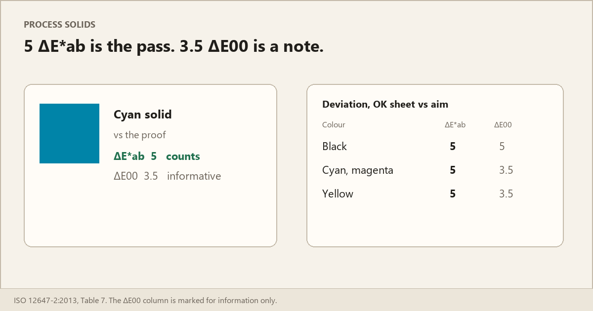
Table 7, for the OK print, deviation tolerance, cyan: 5 ΔE*ab. Beside it, 3.5 ΔE00, and the footnote says the ΔE00 values are information only. The variation tolerance, for production copies against the OK sheet, is 4 ΔE*ab for cyan, with 2.8 ΔE00 again only as information. There is also a ΔH of 3 on the cyan row. Black's ΔH cell is a dash. The variation column is the wrong column today. It is the limit for at least 68% of the copies once an OK sheet exists, colour difference against that OK sheet, not against Table 5. We do not have a signed OK sheet. The gate in front of me is the deviation, 5 ΔE*ab, cyan solid against CD1.
I read B, the zone 4 cyan solid, same instrument, same backing, same M1.
Zone 4: L* 52.4, a* -30.8, b* -46.5.
Against 56, -36, -51 the differences are ΔL* -3.6, Δa* 5.2, Δb* 4.5. Square them: 12.96, 27.04, 20.25. Sum 60.25. Square root 7.76. That is ΔE*ab, the 1976 difference, which is the ΔEab column of Table 7. 7.76 is outside 5.
In words, the solid is darker than CD1 by 3.6 L*, and greyer: a* is 5.2 less green than -36, b* is 4.5 less blue than -51. The sky is not a light cyan that wants feeding. It is a heavy, dirtier cyan.
Zone 5, because the picture crosses the key boundary: L* 52.7, a* -31.1, b* -46.9.
Differences from CD1: ΔL* -3.3, Δa* 4.9, Δb* 4.1. Squares 10.89, 24.01, 16.81. Sum 51.71. Square root 7.19. Also outside 5. Against zone 4 the two solids are 0.58 ΔE*ab apart, which is the same fault seen from the next key, not a second problem. If I ease only zone 4, the sky gets a stripe 90 mm wide where zone 5 did not follow. Both keys have to come down, and they have to come down together.
Then I read D, so he could see the patch in his hand on the same aim.
Zone 7: L* 58.2, a* -38.4, b* -53.6.
Differences from CD1: ΔL* 2.2, Δa* -2.4, Δb* -2.6. Squares 4.84, 5.76, 6.76. Sum 17.36. Square root 4.17. Inside 5.
Zone 7 is lighter than the aim, and a bit cleaner, more green and more blue. His eye had that right. A lighter solid at the end of the strip is a real lighter solid. Feeding that one key would move zone 7 toward CD1, and zone 7 is already inside 5, in a zone note 2 lets me leave out. It would not touch the sky. Feeding the whole cyan because that patch looked thin is the move that hurts: zone 4 is already 3.6 L* darker than 56, and more ink there makes it darker. The key in his hand was the wrong key. The sky's keys, zone 4 and zone 5, have to come down.
I did not turn 7.76 into a CIEDE2000 number at the bench and then hold it against 3.5. The 3.5 is the informative column. A conversion done in a hurry is how those two columns get swapped, and the footnote is there so they do not. The normative deviation on that row, the one clause 4.3.2.3 points at when it says Table 7, is 5 ΔE*ab. We had already missed it. I also did not work out ΔH. The table lists 3 for cyan. I did not need a separate hue test to decide a solid that had already failed on ΔE*ab. Had zone 4 been inside 5 and still looked skewed, ΔH would have been the next thing to calculate properly, not to guess. That was not this sheet.
| Place on this sheet | L* | a* | b* | Aim, white backing | Result |
|---|---|---|---|---|---|
| Paper, tail margin of zone 4 | 94.2 | 0.8 | -3.4 | PS1 95, 1, -4 | inside ±3, ±2, ±4 |
| Cyan solid, zone 4 | 52.4 | -30.8 | -46.5 | CD1 56, -36, -51 | 7.76 ΔE*ab, outside 5 |
| Cyan solid, zone 5 | 52.7 | -31.1 | -46.9 | CD1 56, -36, -51 | 7.19 ΔE*ab, outside 5 |
| Cyan solid, zone 7 | 58.2 | -38.4 | -53.6 | CD1 56, -36, -51 | 4.17 ΔE*ab, inside 5 |
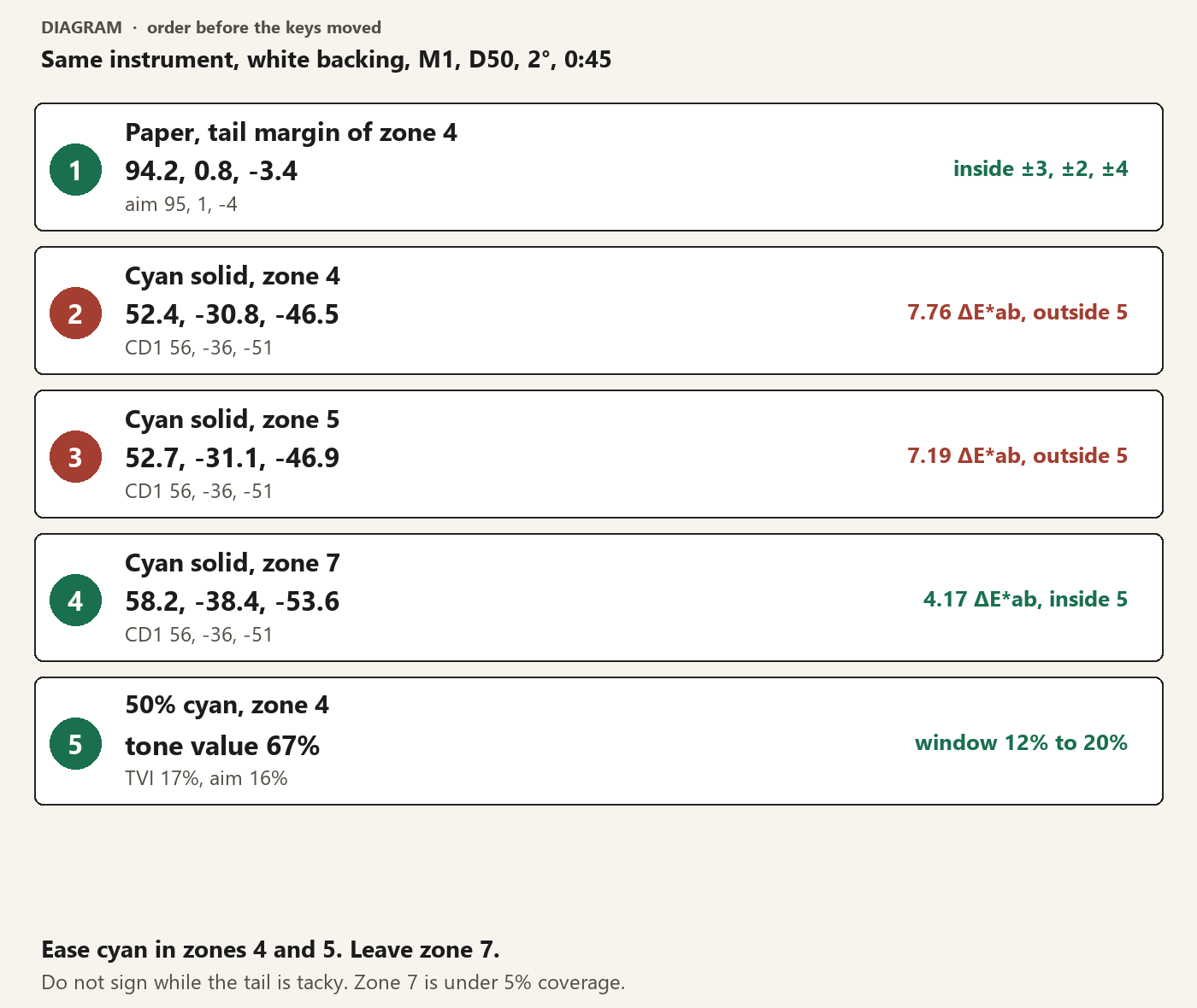
That order is the order on the bench. Paper, sky, the other half of the sky, then the patch that started the panic. The 50% patch is on the drawing because I did read it, and it is last on purpose.
The same drawing is why I would not average the three cyan solids and announce a form average. An average of 7.76, 7.19 and 4.17 is a number the sheet never printed. Zone 7 is allowed out of the conformance set by the 5% note. Even if I kept it in, averaging it with the sky would make the sky look closer to a pass than zone 4 is. The customer buys the sky. The sky is zone 4 and zone 5.
The 50% patch does not get to steer a solid that is already outside
Table 8 gives tone value increase for the control patches. PC1, periodic screens, at the 50% patch: 16%. The same row at 40% is 15%, at 75% is 13%, at 80% is 11%. The non-periodic half of that row, at 50%, is 28%. Same table, same printing condition, the other screen. Our plate is periodic. The aim I am allowed to use is 16, not 28. I looked at that before I let anyone call the mid-tone heavy or light. It is an easy miss when the control computer shows one TVI curve and the plate was imaged with the other.
Table 11 is the tolerance on that increase. For a control patch from 30% to 60%, the OK-print deviation tolerance is 4 percentage points, and the production variation tolerance is also 4. Mid-tone spread, the spread between the chromatic colours, is 5 at most. Note 1 says the percentages refer to a control strip whose screen ruling is the same as the subject. Our strip matches the 70 cm-1 periodic dot. Note 2 says you get the result by subtracting the aim from the measured value.
Table 8 note 1 says those TVI figures come from densitometry to ISO 5-3, ISO Status E, no polarisation. Note 2 says Status T on standard inks comes out close. I did not rely on "close". The densitometer was on Status E, polariser out, before I accepted the mid-tone number. Clause 4.3.2.3, in the note on density, is blunt about the other use of a densitometer: density is useful for holding a run once the instrument, the ink and the paper stay the same, and it does not define a colour well enough for this standard. The usual order is the one in that note. Get the solid colour right, then read the densities off the OK sheet, then hold the run to those densities. We were not at that step. The console density from the previous form stayed on the console.
The 50% cyan patch in zone 4 read a tone value of 67%. The file value is 50%. TVI is 67 minus 50, which is 17%. Aim 16, deviation tolerance 4, so the window for an OK sheet is 12% to 20%. Seventeen sits inside it. The dot on that patch was still round when I looked at it with a glass. I was looking for a smear or a double, because a slurred mid-tone is a mechanical fault and not a key. I did not see one. I am not putting a slur tolerance on this sheet. I did not have one I was willing to treat as a number from the standard. I only needed to know I was not about to cut ink in order to fix a dot that was already doubling.
Seventeen inside 12 to 20 means I do not open a plate curve, and I do not ask prepress for a new cyan compensation, while the solid in the same zone is 7.76 ΔE*ab outside the deviation. The solid is the ink film in that key. The mid-tone is behaving. Fix the film. If, after the solid is back inside 5 and the sheet is dry, the 50% patch is then outside 12 to 20, that is the moment the curve becomes the subject. It was not the subject at 17%.
Clause 4.3.6 note 3 says a zone with such high coverage that the tone-value reading is not reliable can be left out of the TVI check. The sky is heavy coverage. I did not measure TVI inside the picture. I measured the 50% patch in the strip, which was intact. That patch is what Table 8 and Table 11 are talking about.
I did not compute a mid-tone spread. Spread is the variation between the chromatic colours, and the limit is 5. Magenta and yellow were not the complaint, and I was not going to invent a spread from two colours I had not written down. Cyan's own TVI was enough to decide that the curve was not today's lever.
What I turned, and what I will not sign while the tail is tacky
I took a short turn off the cyan keys for zone 4 and zone 5, both the same way, and I left zone 7 alone. I did not touch magenta, yellow or black. Their solids were not the patch anyone was pointing at, and I had not read a failure on them, so they did not get a courtesy adjustment "while we are here". Courtesy adjustments are how a passing black becomes tomorrow's complaint.
Then I pulled another sheet and laid it on the same white backing. The tail was still tacky. Clause 4.3.2.3 and the captions under Table 5 give the aims for dry sheets. Note 5 of clause 4.3.6 says conformance measurements can be made on dry sheets, after a time that depends on the process and the materials. The standard does not give me a dryback allowance to subtract from 7.76, and I will not invent one. A tacky reading can move. It cannot move, in any number I am willing to use, from a clear miss to a pass I sign. The direction was already obvious: zone 4 and zone 5 were darker and greyer than CD1, by more than the whole deviation. Less cyan in those two keys is the direction. How far the dry solid lands is a second reading, on a dry sheet, in the same places, with the same instrument, on the same backing, in M1.
So the second sheet did not become the OK sheet. I pencilled the wet numbers in the margin — zone 4, 52.4, -30.8, -46.5, 7.76; zone 5, 52.7, -31.1, -46.9, 7.19; zone 7, 58.2, -38.4, -53.6, 4.17; paper 94.2, 0.8, -3.4 — and I left the signature line empty. The pencil is so the next reader does not have to reconstruct which patch was outside. It is not a pass.
When a dry sheet from this form is read, the gate is the same gate. Paper still has to sit inside ±3, ±2, ±4 of 95, 1, -4 if anyone wants to reopen the stock. Zone 4 and zone 5 cyan, white backing, M1, D50, 2°, 0:45, against 56, -36, -51, deviation 5 ΔE*ab. Not 3.5 ΔE00. Not the variation of 4 ΔE*ab, which is a production limit against the OK sheet for at least 68% of the copies, and which does not exist until somebody signs. Zone 7 stays out of the decision unless the picture grows into that zone. The 50% cyan patch, Status E, no polariser, periodic aim 16%, window 12% to 20%, gets looked at after the solid is inside, not before.
The digital proof comes back only as the visual check note 5 describes, once the solids in the sky's own zones are no longer 7 ΔE*ab adrift of the data set the proof was made from. Looking at the proof first, this afternoon, is how he ended up trusting a thin patch at his elbow. The proof and the sky can be discussed when zone 4 and zone 5 are actually near CD1. They were not.
A passing solid can still leave the picture looking wrong. That is a different sheet from this one, and it is written up in When a Delta E pass still looks wrong. This cover did not pass. The patch that looked like a pass was in the wrong zone.